Questioning Sheet Metal Simulation for Sand Casting Design
Learn when sheet metal simulation falls short in sand casting design and how to choose better modeling methods for accurate aluminum cast parts.
Many engineering teams are very comfortable with sheet metal simulation. It is already part of the CAD tools, it feels quick, and it gives fast answers when a project is under pressure. So when a new aluminum sand casting program shows up, it can be tempting to push the same buttons and hope the same rules apply.
That is where problems start. The basic assumptions that make sheet metal simulation work do not match what really happens when molten aluminum flows into a sand mold, cools, and shrinks. In this article, we walk through where that gap shows up, what it costs, and how purpose-built casting simulation, combined with foundry experience, can keep new programs on track instead of slipping into late-year delays and rework.
When Sheet Metal Rules Mislead Sand Casting Designs
Sheet metal tools were built for a different world. They expect flat blanks, bends along clear lines, and small shape changes in solid material. When those tools are used to explore sand cast parts, they can give a false sense of safety.
Sheet metal simulation usually bakes in ideas like:
- Uniform thickness across most of the part
- Simple bend or stretch behavior
- Very small or no volumetric change in the material
A sand casting lives in a different reality. Molten aluminum must fill a 3D mold cavity with ribs, bosses, and changing wall sections. It has to cool and shrink in a controlled way. That behavior is not captured when a model is treated like a formed sheet.
If design teams do not question that gap early, they can walk into peak production season with parts that looked fine in a sheet metal study but fail in real pour trials. That is when scrap climbs, pattern changes pile up, and late builds slip.
Why Sheet Metal Simulation Falls Short for Cast Aluminum
The root issue is simple: sheet metal simulation looks at how solid material deforms, while casting simulation looks at how liquid metal flows and freezes. Those are not just different settings in the same tool, they are different physics.
Sheet metal models tend to assume:
- Mostly constant wall thickness
- Defined bend lines and limited forming zones
- Stresses from stretching and bending solid material
Sand cast aluminum needs tools that track:
- Fluid flow into thin and thick sections
- Heat transfer between metal and sand mold
- Solidification paths and where metal freezes first
Casting geometry is full of thick bosses, thin walls, fillets, and junctions that heat and cool at different speeds. Under real thermal and metallurgical loads, those features create hot spots, shrinkage cavities, and stress concentrations that a sheet metal model will never see.
When a team leans on sheet metal simulation for a casting, they often miss:
- Hot spots that turn into shrink porosity inside the part
- Internal voids where metal stopped feeding during solidification
- Distortion that only shows up after machining
- Residual stresses that appear later in fatigue or pressure tests
By the time those issues show up, the part may already be deep in a launch schedule, with tooling released and machine programs written.
Hidden Costs of Treating Castings Like Formed Sheet
The real pain starts in the design stage. A model shaped by sheet metal habits can look nice on screen and still be very hard to cast.
Common issues that get locked into the 3D model include:
- Draft angles that are too small or missing
- Thin junctions between thick and thin sections
- Sharp corners where metal struggles to feed
- Features that block room for gates and risers
Once that model turns into patterns and tooling, each fix becomes an engineering change order. Pattern rework, extra trials, new simulations, and updated machining all take time. When schedules are tight, those weeks often land right before important build events.
Downstream, treating a casting like formed sheet can cause:
- Extra X-ray or other non-destructive testing loops
- More weld repair or scrap than planned
- Tooling re-makes when simple rework is not enough
In demanding applications like transportation and industrial equipment, missed feeding paths and poor shrinkage allowances can also show up as:
- Inconsistent tensile properties from part to part
- Poor fatigue life in high-stress zones
- Surprises during assembly when distortion pulls key surfaces out of spec
All of this adds up to missed dates and quality concerns that could have been flagged at the 3D model stage with the right casting view.
What True Sand Casting Simulation Does Differently
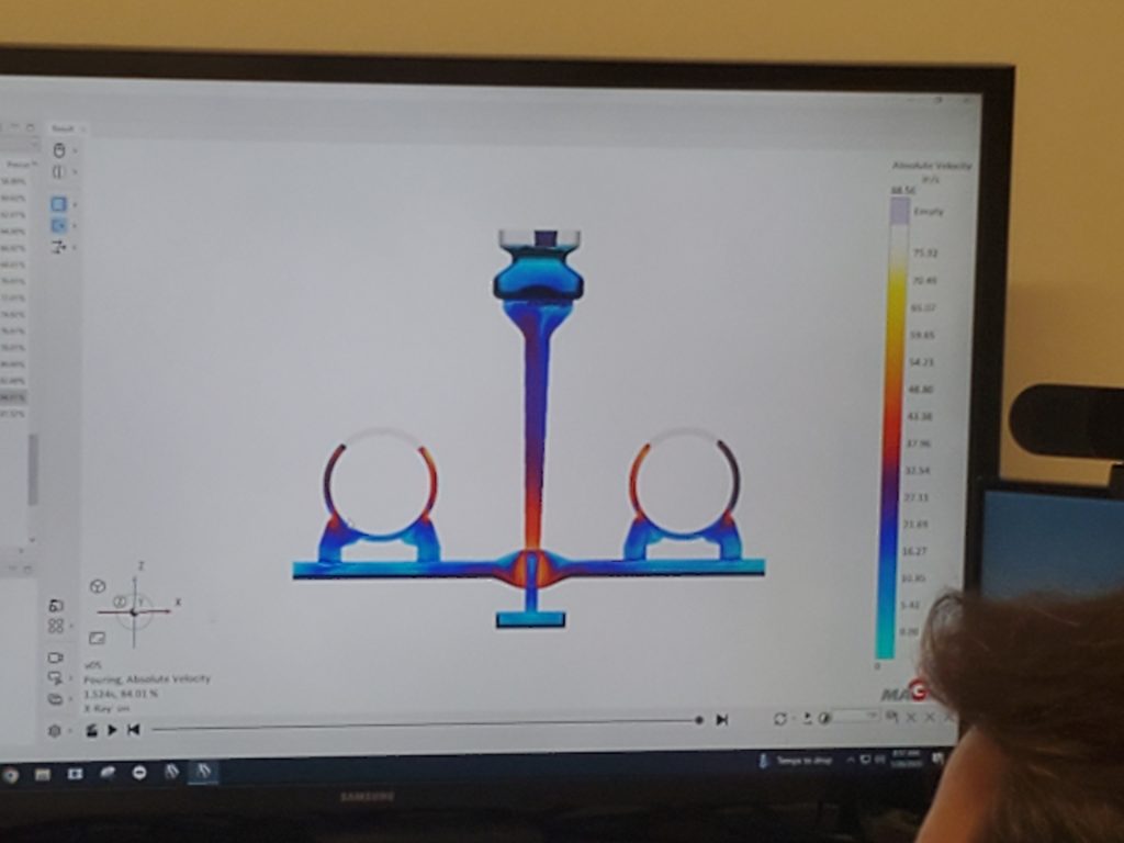
Purpose-built casting simulation tools are designed around the reality of molten aluminum in sand molds. They model how metal flows, where it slows, how turbulence creates gas entrapment, and how the part freezes over time.
Key inputs for a casting simulation include:
- Alloy chemistry and expected pouring temperature
- Mold and core materials and their thermal behavior
- Gating and riser design, including choke points and feeder sizes
Instead of simple strain or bend plots, casting simulation outputs:
- Predicted shrinkage zones and isolated hot spots
- Feeding effectiveness of risers and gates
- Areas at risk for porosity or lack of fusion
- Expected distortion patterns and mechanical property gradients
Used early, these tools become a design partner. We can run virtual trials, tweak wall transitions, move or resize risers, and shift gates without touching physical tooling. Each loop brings the part closer to a design that pours cleanly and moves faster toward first article or PPAP approval.
Collaborating Early to Turn Concepts Into Castable Designs
The best time to protect a casting program is at the concept or early prototype stage. When design teams bring models to a foundry partner before everything is frozen, we can help them move away from sheet metal habits that fight the sand molding process.
A typical workflow at BQC Foundry looks something like this:
- Review of the 3D model with casting-specific DFM in mind
- Discussion of function, loading, and critical surfaces
- Dedicated casting simulation of mold filling and solidification
- Pattern and process design tuned to real melting and molding conditions
We also look at how the casting will be machined and assembled, not just how it will be poured. That cross-functional view helps balance:
- Weight targets versus casting yield
- Cost versus tooling complexity
- Performance versus process stability
By bringing design engineers, manufacturing engineers, and foundry experts together, teams can agree on where to add material, where to remove it, and how to shape features so the part is both castable and easy to finish.
Rethink Your Next Project Before You Hit Run on Simulation
The next time a part is marked as aluminum sand cast, it is worth pausing before clicking the usual sheet metal simulation button. A small mindset shift can prevent a long list of late surprises.
Helpful steps for design teams include:
- Flag components that will be sand cast early in the project
- Run a quick castability review on ribs, bosses, and junctions
- Identify critical features that truly need casting simulation
- Update internal checklists so formed and cast parts follow different rules
At BQC Foundry, we see our role as helping teams move from a solid model that works in CAD to a casting that works in the mold, in machining, and in final service. Questioning sheet metal simulation at the start is often the first and most important step in that path.
Get Started With Your Project Today
If you are ready to reduce costly rework and validate your designs earlier, our team is here to help you apply advanced sheet metal simulation to your next project. At BQC Foundry, we collaborate with your engineers to uncover risks before they reach the shop floor and to optimize manufacturability from the start. Share your design requirements and production goals, and we will outline a clear path to more reliable outcomes. To discuss your timeline, budget, and technical needs, simply contact us today.